Limitations
- The initial cost of equipment is relatively high.
- The build material choices for different processes unlimited in terms of their properties. in some cases, only plastic materials could be used.
Applications
some areas of the uses of rapid prototyping are
- checking the feasibility of new design concepts
- making functional models with the limitation of the material to do any testing
- conducting market evaluation
- creating tooling for metal casting, injection moulding ,and some metal forming processes
- building a prototype sand or metallic moulds and cores for sand, permanent mould and die casting
- fabricating a master pattern for Silicon and epoxy moulds
- manufacture many exact copies of models simultaneously
Typical steps involved in all RP techniques:
- A CAD model is constructed and then converted to STL (standard triangular language) format to input into the software for creating the slice data.
- The software processes the STL file by creating sliced layers of the model. the resolution of the built model belt depends upon the layer thickness.
- The RP device creates the first layer of the physical model.the model is then lowered by the one layer thickness, and the process is repeated until the model is completed.
- The model and any supports are removed; the surface of the model is then finished and cleaned.
RP techniques
- Stereolithography (SLA)
- Selective laser sintering (SLS)
- Fused deposition modeling (FDM)
- 3D printing (3DP)
- Laser engineering net shaping (LENS)
STEREOLITHOGRAPHY
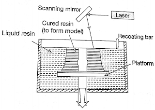
The most commonly used process for Rapid prototyping is stereolithography or photolithography. These systems build shapes using light to selectively solidify photocurable resins. A stereolithography machine converts three dimensional CAD data of physical objects into vertical stacks of slices. A low power ultraviolet laser beam is then carefully traced across a vat of photocurable liquid polymer, producing a single layer of solidified resin- the first slice of the object under construction. The laser beam( UV Helium- cadmium or Argon) is guided across the surface( by Servo controlled Galvanometer Mirrors) drawing a cross-sectional pattern in the x-y plane to form a solid section the initial layer is then lowered incrementally by the height of the next slice. A re-coating blade passes over the surface to ensure that a consistent layer thickness is achieved. The re-coating blade was found to be necessary without which air Entrapment caused build problems. This procedure is repeated until the entire part is fabricated.
 |
| Stereolithography |
Accuracy available with these machines is much higher compared to the other RP machines. As a result, it is widely used for a number of different applications. This resulted in the development of a number of Machines to Cater to the different applications with different part sizes ranging from 250 X 250X 250 mm to 650 X 350X 300 mm.

Post a Comment
Post a Comment